The Gray Pixel
Bryce - Importing lDraw Files
This tutorial will guide you through the process of importing a simple model into Bryce. The steps outlined in this tutorial will work for Bryce2 through Bryce6. The model I have chosen is extremely simple and will allow you to move through the steps quickly and prepare you for the more advanced Bryce import tutorial. This may seem like a long tutorial for something I have labeled Simple Import. Trust me this process is simple and fairly quick.
STEP01::Acquire The Model
You will either need to build set 1642 or download it from this site.
STEP02::Modify The Model Part 1
Using MLCad open the file 1642.dat. We need to make a few modifications to the file before we convert it to a DXF for Bryce. First add a 1x1 brick so it is centered above the model. Look at the following image for reference. Once the brick has been placed color purple.
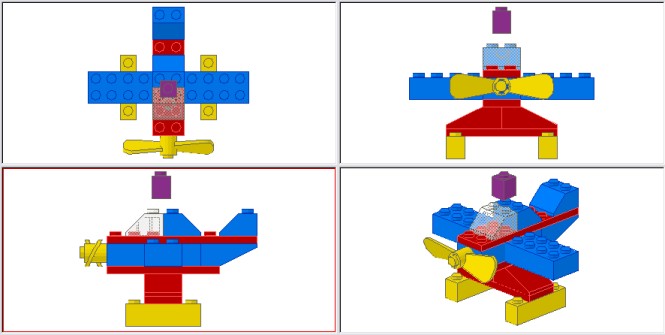
Now the reasons for madness of adding this one brick. If you have used any of my models you will find that they are all scaled the same. This 1x1 brick is used to set the scaling once the model is imported into Bryce. Also when you get to the advanced import tutorial you will find that this brick is extremely critical when importing larger more complex models.
STEP03::Modify The Model Part 2
Now for something extra. This step is a small sample from the advanced tutorial. In MLCad add a Bar 4L Light Sabre Blade to the scene and center on the prop. Look at the following image for reference.
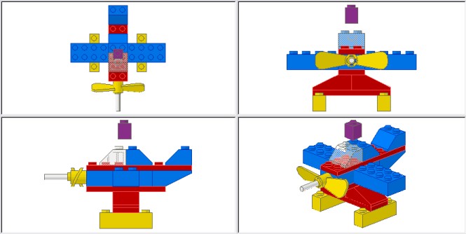
Now the reasons for madness of adding this part. This part will be used as a reference within Bryce so we can make the prop movable for animations or other for simple posing.
STEP04::Modify The Model Part 3
To make sure that we can animate the prop once it is in Bryce we will need to change the color of the prop. Select the prop and make it pink. If you reference my tutorial on the Basic of DAT2DXF you will that the software groups parts by color. Since we to animate the part we will need to separate the yellow prop from the yellow floats.
STEP05::Save Model
Save this file in a directory of your choice as 1642_Bryce.dat. You can use another filename, but I like to keep the original filname and simply the _bryce to the filename to help me keep track of my models easier.
STEP06::Convert Model to DXF
Launch the DAT2DXF conversion software. You should see a window appear that looks something like the following.
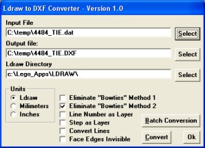
If this is the first time you have used the software you will want to look at my other tutorials about getting the software configured properly for converting models.
Select the 'Input File', this will be the 1642_bryce.dat file you saved earlier. Once the file has been selected click the 'Convert' button to begin the conversion process.
STEP07::Bryce Import
Ok, now the fun really begins. You will need to launch Bryce and create a new scene. When importing models I like to use the 'Simple White Background' Sky preset. This provides a simple lighting and less screen clutter while you are working your model.
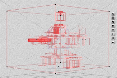
From the menu select File/Import Object. Browse to the DXF file generated by DAT2DXF and click 'Ok'. Bryce will import the model and you should see something like the following.
STEP08::Smooth The Model
Right now if you render the model you will see the basic colors, but if you get in real close you will see that some of the parts are a little rough around the edges. While the model group is selected we need to smooth the model so it will look much nicer in the final render. Again while the model is selected click on the 'E' button. This will bring up a window that will allow you to select what degree of smoothing need to be applied to the model.
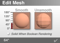
On the left side of the screen you will see what look like temperature guage. This is a slider bar that will allow to adjust the smoothness. I have found that if you select 64 the smoothed model looks quite nice.
STEP09::Setup Model Scaling
Ok this next step is kind of tricky if you are not used to working with grouping and linking in Bryce. I guarantee you will get used to it and become an expert before too long. Mastering these two techniques will help you greatly in any Bryce project.
The model group should still be selected. Now click on the 'U' button. This will Ungroup all of the parts. Ok now for the tricky part, hold the shift key and click on the 1x1 Brick. This will deselect the part from the currently selected group of parts. To finish there is a button that has three little squares lined up diagonally. It is located third from the top of command buttons listed next to the selected parts. Click and hold this button, then drag it over the 1x1 Brick. When you drag the button over the brick, the part will become hi-lited. When the part is hi-lited you let go of the mouse button. If this was done correctly you should be able to grab the 1x1 Brick and drag across the screen and the other parts should follow.
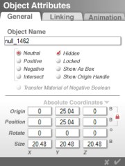
Now select the 1x1 Brick. A list of command buttons will appear next to the part. Click on the 'A' button. This will open a new window. Enter the following values into the screen.
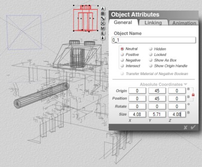
Again if the linking process was done correctly the rest of the model should resize in proportion to the change in the 1x1 Brick. The size 4.08,5.71,4.08 is the scaling I use for all of my models. This allows to make sure that all of my models are setup to the same scale.
STEP10::Establish Reference Points
The following is another technique that you will find very useful when working models in Bryce. This technique is especially useful for controling objects in animations, but that is another tutorial.
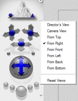
First change the view so that we are look at the model from the right.
Add a sphere to the scene and position it so that the botton of the sphere lines up with the bottom of the plane.
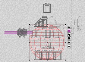
Finally set the sphere properties to the following. It is important to give objects good name so they can be easily referenced later. Also color code the sphere to Family 11. This is my personal choice that I use for all of my models. By color coding I can either select objects by color so I can retexture multiple parts at once or just to be able to simple identify how a part is used.
Add a cylinder to the scene. You will need to rotate the cylinder so it is laying horizontally. Earlier in this tutorial I asked you to added 4L Bar to the model centered on to the prop. Well now we are going resize and reposition our cylinder so that it matches the position of the 4L Bar. You can do this for yourself or you can take a shortcut and use the following parameters.
While the cylinder is selected you will now need to link the cylinder to the sphere. As demonstrated earlier click and hold the button with the three little squares and drag it over the sphere. When sphere is hi-lited, let go of the mouse button to link to the sphere. Now select the 4L Bar part and delete it from the scene since it is no longer needed.
STEP11::Texture and Link
I already have a group of preset textures available for download. You can use these or your own textures for the following step.
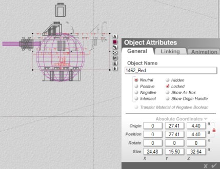
You can use the Tab key to move through the all of the objects currently in your scene. Press the Tab key to move to the next part of the airplane model. The following example shows the selection of the red part. Change the name of the part name and properties to the following. When this is done, color code the part to family 21, link to the sphere, and apply the appropriate material preset.
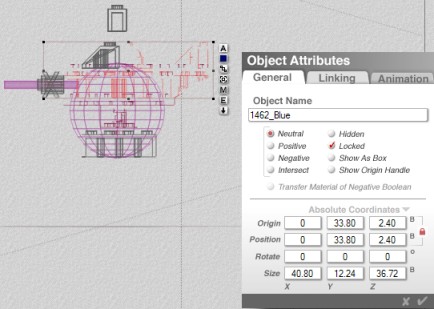
Press the Tab key to move to the next part of the model. The following example shows the selection of the blue part. Change the name of the part name and properties to the following. When this is done, color code the part to family 22, link to the sphere, and apply the appropriate material preset.
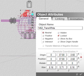
Press the Tab key to move to the next part of the model. The following example shows the selection of the trans-white part. Change the name of the part name and properties to the following. When this is done, color code the part to family 2, link to the sphere, and apply the appropriate material preset.
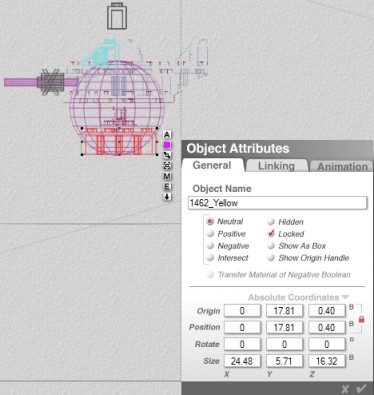
Press the Tab key to move to the next part of the model. The following example shows the selection of the yellow part. Change the name of the part name and properties to the following. When this is done, color code the part to family 3, link to the sphere, and apply the appropriate material preset.
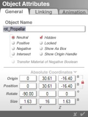
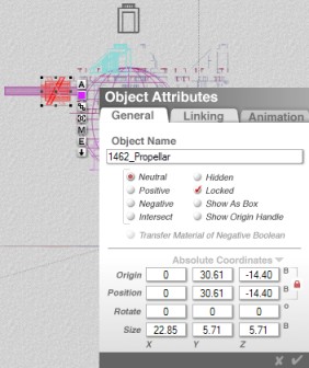
Press the Tab key to move to the next part of the model. The following example shows the selection of the propellar. Change the name of the part name and properties to the following. When this is done, color code the part to family 3, link to the cylinder, and apply the appropriate material preset.
Now the last part of the model is the 1x1 Brick. At this point if all of the linking was done properly you should be able to select this part and delete it from the scene. If any other part disappeared with the 1x1 Brick press Ctrl-Z to undo the deletion, then go back link the part to the sphere.
STEP12::Quick Check
Ok lets make sure that everything has been accomplished properly. First, the only things in your model that can be selected are the sphere and the cylinder. Second, make sure the propellar is linked to the cylinder by trying to rotate the cylinder. If the linking was done properly then the propellar should rotate with the cylinder. Finally, all of the parts should be linked to the sphere. Test this by trying to move or rotate the sphere.
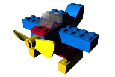
STEP12::Test Render
Ok lets make sure that everything has been accomplished properly. First, the only things in your model that can be selected are the sphere and the cylinder. Second, make sure the propellar is linked to the cylinder by trying to rotate the cylinder. If the linking was done properly then the propellar should rotate with the cylinder. Finally, all of the parts should be linked to the sphere. Test this by trying to move or rotate the sphere. If this is all good then render the model. Hopefully you will get something like the following.
STEP13::Save The Model
Time to save the model. We do not want to lose all of our hard work. Typically I do two saves. The first save is to a file on my hard drive. The second save is to the Bryce Object Preset Library. If you are unfamiliar with this then click on the triangle to the right of the 'Create' label at the top of the screen. This will open a new window showing you the various object libraries. Select a library and click on the 'Add' button. This will add our new airplane model to the library. Now the next time you need the model for a scene you can simple go to the library select it to add to your scene.